- Kits
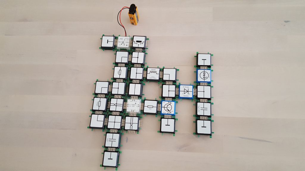
Timer 555 as voltage generator
The timer as an up converter or booster
Sophie Seewald
English
Advanced
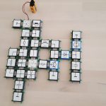
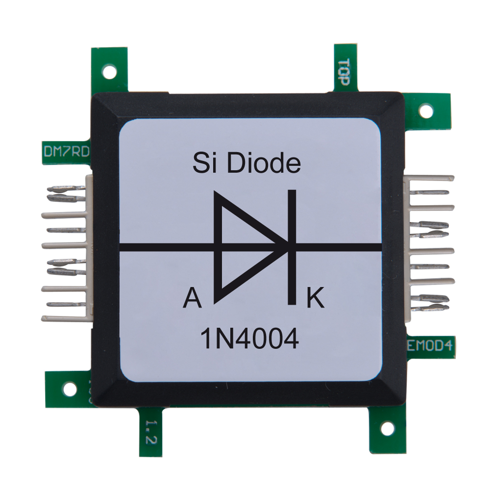
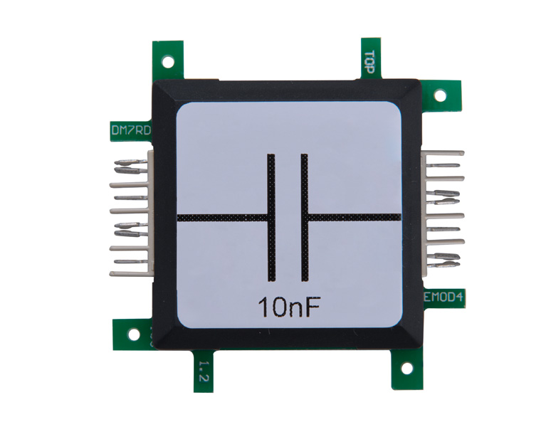
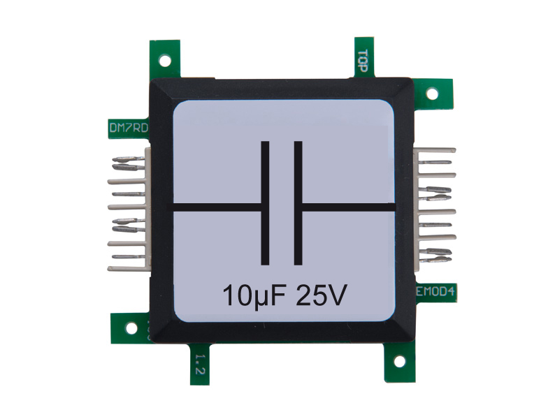
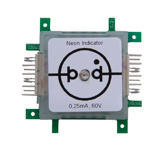
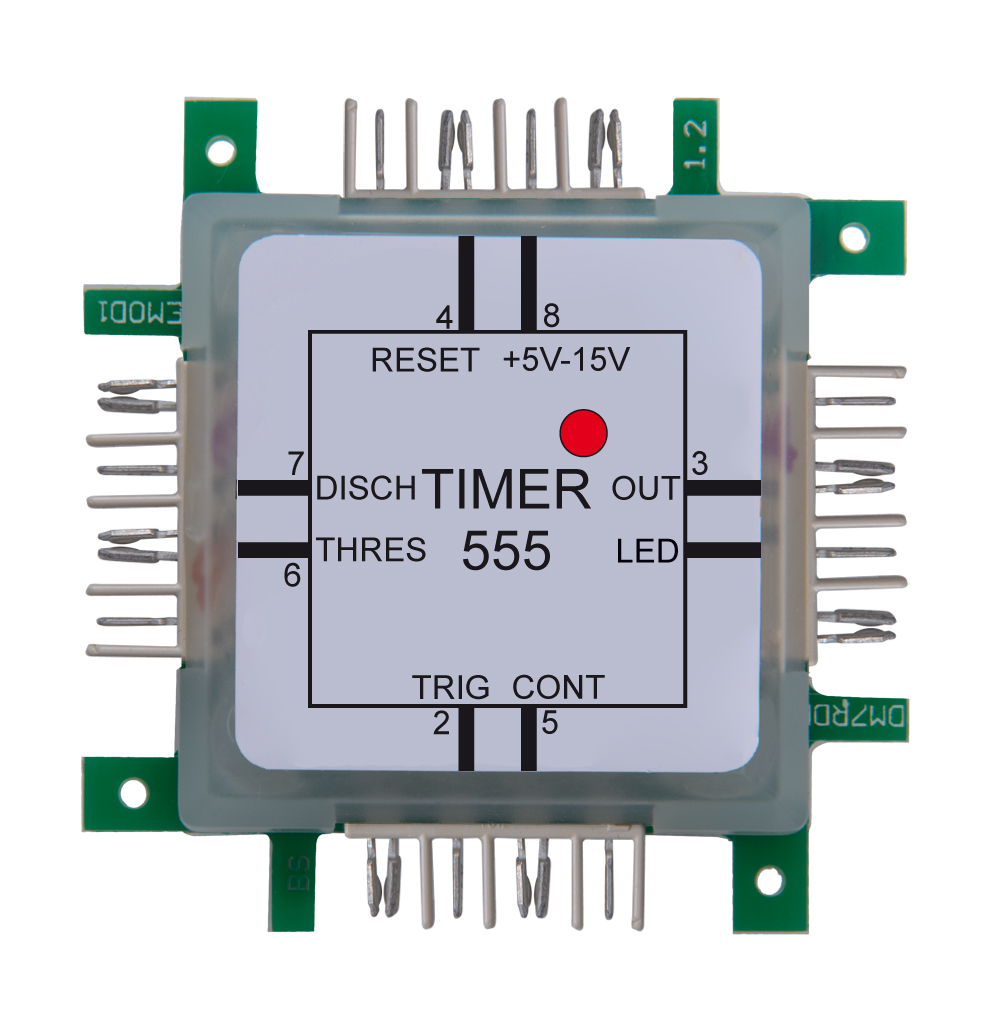
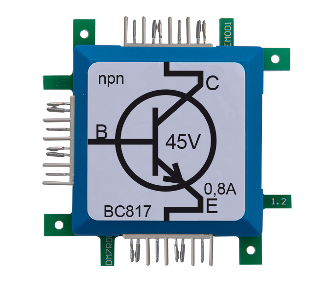
The timer 555-brick specifies the frequency, which is used by the transistor to charge and discharge the coil. The output of the timer switches the transistor on and off. Since the change of the current flow takes place in a very short time, the inductive voltage is very high. The switching frequency of 670Hz is too high to be seen by the naked eye. The gas discharge lamp is connected to a capacitor which is charged by use of a rectifier diode. The capacitor is necessary, because the single event of the coil inductance does not carries enough energy to light the gas discharge lamp. It stores the energy until the ignition voltage of approx. 60V is reached.
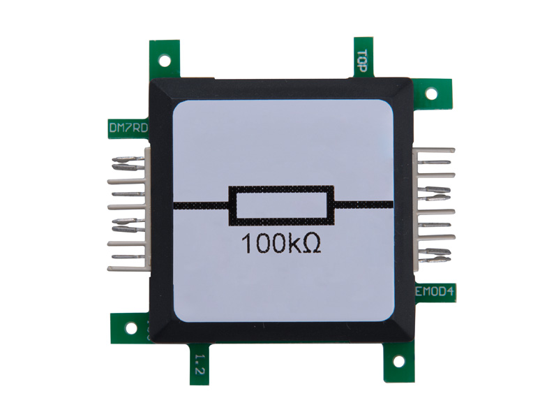
After ignition, the capacitor is discharged and the process starts again. The interesting thing about this circuit is that it can produce a higher voltage than provided by the power-supply. Increasing the voltage by a combination of coil and capacitor is used in fluorescent tubes or backlight TFT or LCD screens. This circuit is also called upconverter (boost converter) or booster (amplifier) and is used in transformers or switching power supplies, used for computers. The stabilization of the output voltage is very important and is done in this experiment by the glow-lamp. With the capacitor at the input of the timer 555-brick the switching frequency can be changed. The relationship between resistance and capacitor defines the frequency.


